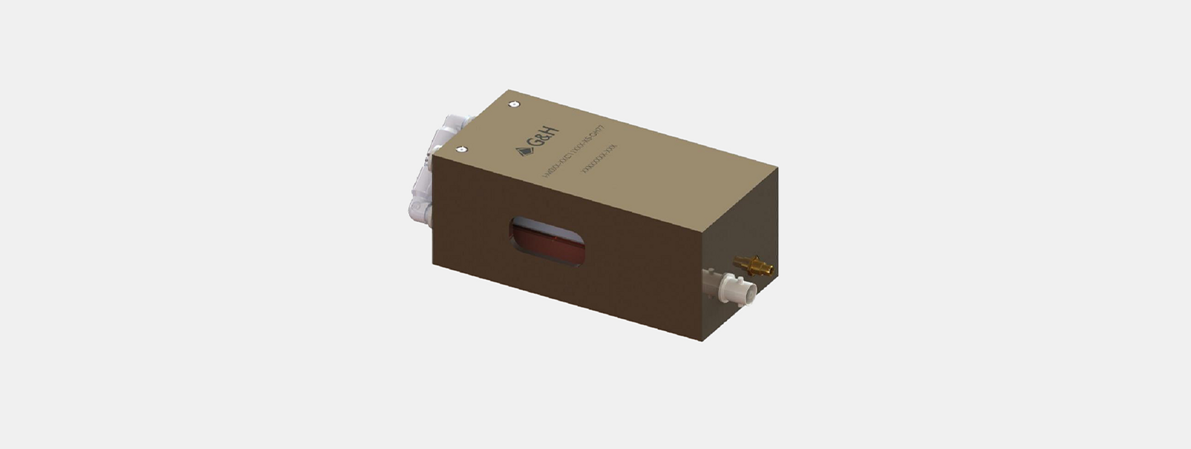
HP041-125ADG-A10
With an operating frequency of 40.68 MHz, a 125 W output into a 50-ohm load, and analog and digital modulation.
Full Product Description- RF output power:
- Max: (adjustable): > 15 W/mm² *, Adjustment range: < 1 … >125 W
- RF output frequency:
- 40.68 MHz
Product description
Water cooling parts made from copper ensure the highest standards for corrosion protection.
Optimum EMC shielding and mechanical protection are achieved by an aluminium casing and conductive surface passivation.
Key features
- RF output power up to 125 Watt
- Copper water-cooling path
- Constant output power design
- High SWR and overheat safety shutdown
- Compact casing, fully shielded (EMC)
Specifications
| Name | Value |
|---|---|
| Device | AO Modulator |
| Supply voltage | +24 VDC |
| Supply current | Max: 12.5 A @ 125 W RF output power |
| RF output power | Max: (adjustable): > 15 W/mm² *, Adjustment range: < 1 … >125 W |
| Output impedance | Nom: 50 Ω |
| RF ON / OFF ratio | > 50 dB |
| Analogue modulation impedance | 600 Ω |
| Analogue modulation voltage range | @ 50 Ω: 0 … +10 V. The voltage range corresponds to 0 to 100% of the potentiometer pre-adjusted max RF output power. |
| Digital modulation | 4.7 kΩ (pull-up) |
| Digital modulation impedance | High = ≥ 3V … 5V (= RF on) |
| Digital modulation level | Low = 0 … < 2V (= RF off) |
| Maximum modulation frequency | 1 MHz (digital and analogue) |
| RF output frequency | 40.68 MHz |
| Harmonics distortion | < -30 dBc * |
| Rise/fall time | Analogue modulation: < 80 ns (10 … 90%) *, Digital modulation: < 80 ns (10 … 90%) * |
* into 50 Ω load
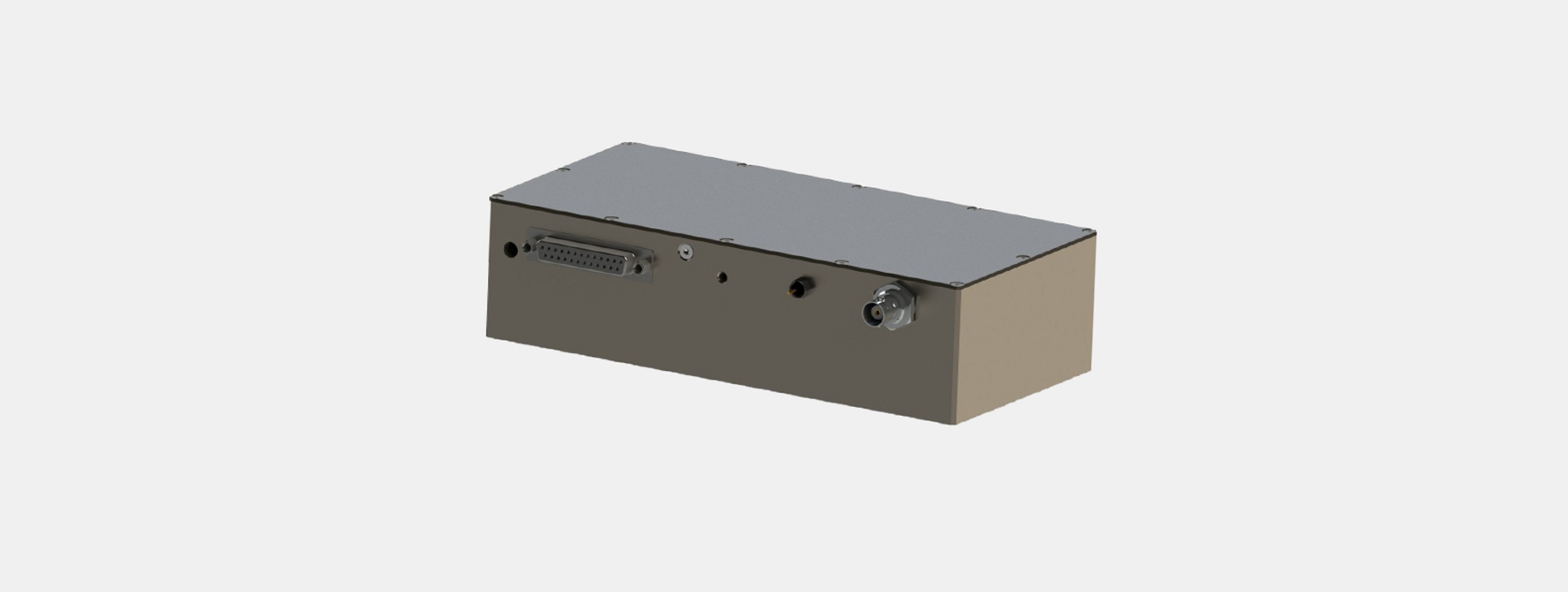
Connectors, Cooling, Dimensions, Weight
| RF output connector | BNC female |
| Control connector | D-Sub 25-pole, female for pin assignment refer to section Control Connector |
| Power supply cords | 2x 750±50 mm H07V-K 1.5 mm² |
| red (or yellow) | + Vs (24 VDC) |
| black (or violet) | CGND (case ground) |
| Cooling | Water cooling. Cooling block material: Copper, 2 x G 1/4’’ thread fitted with 6mm push in connectors. |
| Flow rate | More than 1 litre/minute at less than 25˚C |
| Dimensions [mm] | 200 x 100 x 52.5 (length x width x height) |
| Weight | 1470 grams |
| Environmental Conditions | |
|---|---|
| Warm up time | 10 minutes for optimum stability |
| Operating case temperature | < +50°C, safety shutdown at ≈55°C |
| Storage temperature | -20°C … +65°C, non condensing |
| Absolute Maximum Ratings | |
|---|---|
| Supply voltage max. | +26 VDC |
| Analogue modulation | -0.5 V … +11 V |
| Voltage range @ 0 … +10 V | |
| Digital modulation | |
| Level | -0.5 V … +5.5 V |
| Maximum operating temperature | +55°C heat sink / base plate temperature |
Control Connector
D-Sub 25-pole, female
Any signals refer to chassis ground (CGND) unless denoted differently.
| Pin assignment | |||
|---|---|---|---|
| Pin 1 | RF ON status (out) | Pin 10 | Modulation Ground (MGND) |
| Pin 2 | SWR fault indication (out) | Pin 11 | Analogue modulation 2 (ref. MGND) |
| Pin 3 | Driver temperature fault indication (out) | Pin 12 | Analogue modulation 1 (ref. MGND) |
| Pin 4 | Reset SWR fault / Init (in) | Pin 13 | Power Level Select (ref. MGND) |
| Pin 5 | Interlock 2 fault indication (out) | LOW → select Analogue Mod. 1 | |
| Pin 6 | Interlock 2 (in) | HIGH → select Analogue Mod. 2 | |
| Pin 7 | Interlock 1 (in) | Pin 14…22 | Chassis ground (CGND) |
| Pin 8 | Interlock 1 fault indication (out) | Pin 23…24 | Modulation Ground (MGND) |
| Pin 9 | Driver temperature monitor (out) | Pin 25 | not connected |