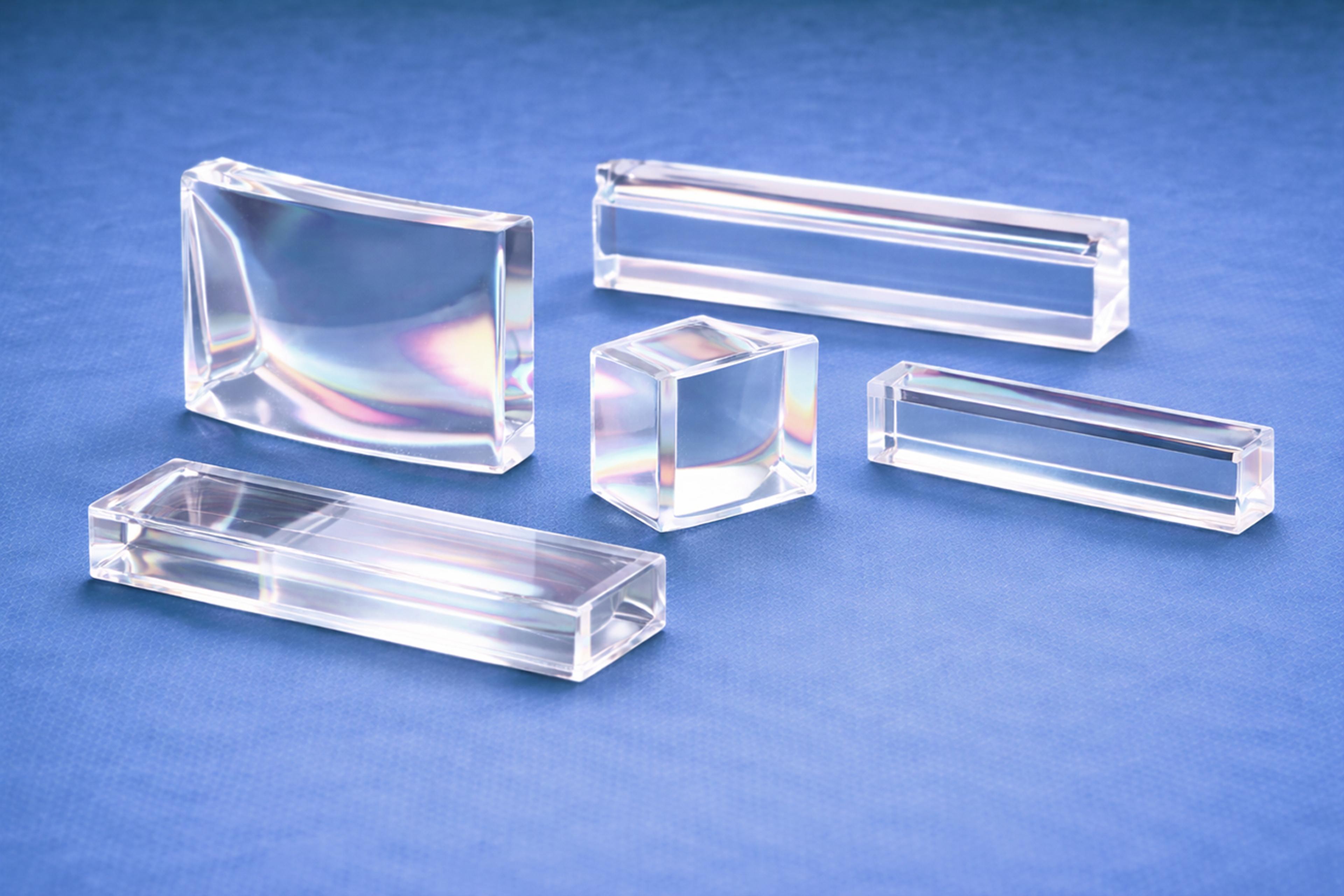
Beam Splitter Polymer Optics
G&H | GS Optics manufactures polymer beam splitter optics for imaging, metrology, and sensing systems.
Full Product DescriptionProduct description
Precision polymer beam splitter optics for imaging and sensing divide or combine light beams with high precision and optical uniformity. At G&H | GS Optics, we manufacture custom polymer beam splitter optics that integrate precision-molded geometry with advanced thin-film coatings to achieve stable, predictable performance across visible and near-infrared wavelengths.
Applications
- Imaging and vision systems – reflection/transmission balance for cameras and sensors
- Optical metrology – precision beam routing and signal measurement
- Laser and photonics systems – wavelength control, polarization management
- Biomedical instruments – beam routing in diagnostic or illumination modules
- AR/VR displays – polarization and wavelength management for compact optics
Core Capabilities
- Custom beam splitter geometries from 5 mm to 100 mm
- Split ratios from 10/90 to 50/50
- ISO Class 7 cleanroom coating and assembly
Key features
Advantages of Polymer Beam Splitter Optics
- Lightweight and durable: Polymers reduce weight and improve mechanical resilience.
- Design flexibility: Molding allows nonstandard shapes and integration with mounts or housings.
- Cost-effective scalability: Replication ensures consistent optical and coating performance across production.
- Broad spectral control: Coatings can be tuned for visible, NIR, or specific laser wavelengths.
- Compact integration: Enables thinner, multifunctional optical assemblies.
Why G&H | GS Optics
Specifications
Engineering Expertise
Based on decades of expertise, G&H | GS Optics engineers provide our customers with DFM recommendations to ensure that their polymer optics programs are successful. Using mold flow simulations, we can model how resin will fill the mold during the injection molding process to better position gates, anticipate where knit lines will appear, and locate difficult to fill spots in the mold. G&H | GS Optics specializes in scientific injection molding which is a systematic, data-driven methodology to produce world class polymer optics.
Prototypes are diamond-turned using Precitech Nanoform 200 and Nanoform X systems, achieving nanometric surface finish without post-polishing. The same tooling precision transfers directly into injection molds for scalable production.
Quality Assurance and Process Validation
All polymer optics produced by G&H | GS Optics are subject to rigorous quality standards to ensure consistent, reliable performance. Each lens is measured using a variety of metrology equipment to verify dimensional accuracy, surface quality, and refractive characteristics.
To reduce risk after transferring from development to production, GS Optics can conduct a process validation through a combination of installation (IQ), operational (OQ), and performance (PQ) qualifications, ensuring process repeatability and consistent optical performance.
Material & Coating Options
Coating Types:
- Non-polarizing beam splitter coatings (NPBS): Equal reflection and transmission over a target wavelength band.
- Metallic coatings (Al, Ag): Broad-spectrum reflection with optional dielectric protection.
| Material | Key Property | Benefits | Typical Application |
|---|---|---|---|
| PMMA (Acrylic) | High optical clarity, excellent coating adhesion | Ideal for visible-range splitters | Imaging and illumination |
| Polycarbonate | Impact resistant, thermally stable | Ruggedized optical modules | Defense and industrial optics |
| COP (Zeonex®, Zeonor®) | Low birefringence, low water absorption | Stable in NIR systems | Sensors, AR/VR, metrology |
| Polystyrene | Cost-effective, smooth replication | High-volume splitter optics | Consumer or disposable systems |
| Standard | Precision | |
|---|---|---|
| Focal length (%) | ±5 | ±2 |
| Radius of curvature (%) | ±3 - 5 | ±2 - 3 |
| Power (fringes) | 10 | 5 |
| Irregularity (fringes / 10mm) | 4 | 2 |
| Scratch / dig | 80 / 50 | 60 / 40 |
| Center thickness (mm) | ±0.1 | ±0.05 |
| Flange diameter (mm) | ±0.1 | ±0.05 |
| Concentricity (mm) | 0.1 | 0.05 |
| Center to edge thickness ratio | 1:1 | 3:1 |
| Surface roughness (Å RMS) | <75 | <60 |