Skip to Content
Share:
Pipeline in snowy weatherPipeline in snowy weather©️ Private

How G&H overcomes lidar and sensing challenges to make remote sense of earth and space

Technical

Lidar (light detection and ranging) is pushing the boundaries of how we analyze, interpret, and understand both earth and space environments from afar – and G&H’s lidar solutions already underpin many international remote sensing projects and programs.

In practice, lidar is one subset of numerous sensing application areas in which we at G&H are active.

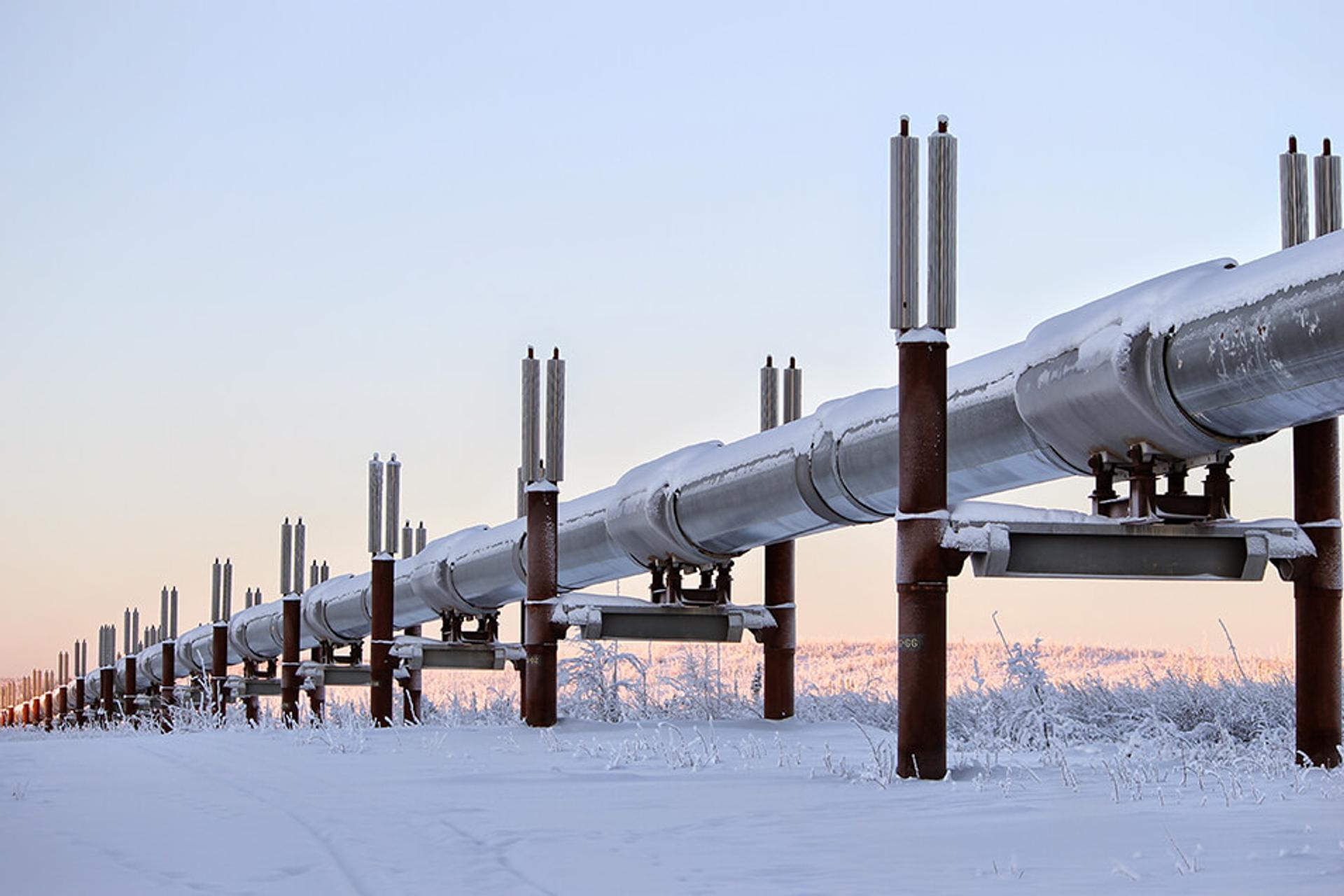
These include distributed fiber sensing, which enables optical fiber to be used as a continuous, real-time sensing medium to detect temperature, pressure, and vibration disturbances over long distances – for example in linear assets such as border fences and walls, oil and gas pipelines, and power and utilities networks.

However, lidar, with its ability not only to locate the exact position of these disturbances, but to sense remotely, rather than in situ, is gaining significantly in traction, and it’s a trend that is likely to continue.

As recent research from experts at the universities of Colorado and Delft asserts, ‘The role of lidar will be increasingly important in the future. Although there are many potentials for new lidar technology advancements, lidar activities are gradually shifting from technology developments to applications.’

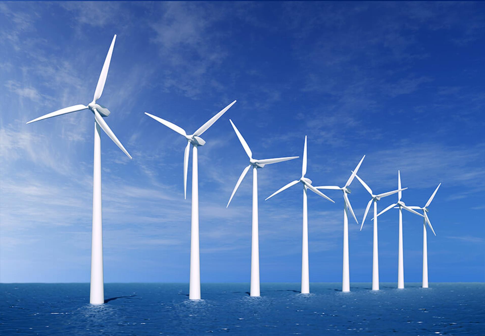
These applications can be anything from wind turbine calibration to spectroscopic analysis of space gases and mineral deposits – and much more besides.

But as the application types and environments proliferate, so too does the scrutiny of the underlying technology and its design. How stable is it? How powerful? How accurate? How sensitive? How susceptible to signal noise, extreme temperatures, shock and vibration?

For OEMs, in particular, the question is also how advanced lidar and sensing technology are in terms of the availability not only of components, modules, and subsystems, but in the design expertise that ultimately informs how these systems will perform.

From technology to applications: lidar makes the leap

Let’s take a look at the demanding parameters photonics solutions must satisfy in a sensing deployment, and specifically for lidar.

Fundamentally, lidar is about transmitting light (or coherent laser light) in pulses through a medium (which can also be space, or the atmosphere), and receiving reflections of that light that convey data about an object’s speed, position, density, spectral composition, and other characteristics.

It therefore follows that for lidar to be reliable in any application, both the transmission and the reception elements must be optimized.

The demands here can be challenging. On the transmission side, sensing applications require extremely narrow spectral width and smooth, stable, tunable control of wavelength, but with scope to also combine and separate those wavelengths to maximize sensing permutations.

They require appropriately variable initial power input, but also strong amplification to enable sensing to take place over long distances (satellite to Earth, for example).

On the reception side, the emphasis must be on increasing sensitivity relative to power and bandwidth requirement, and to tolerate signal impairments.

Add in the application-specific factors, and the challenges grow exponentially. In space, for example, extremes of temperature are common, whilst the space vessels, vehicles and satellites in which lidar systems are mounted naturally encounter significant shock and vibration, not to mention radiation.

Even on Earth, excessive heat, cold and humidity are more than capable of either causing lidar components and systems to fail, or adversely affecting their precision.

How, then, does a lidar system stand up to these challenges and deliver what is required of it?

And how does this response not only benefit other forms of sensing too – including distributed fiber – but create a seamless environment from design to manufacture that supports the development of sensing applications across the board?

Combining components to best effect

The most successful recipes start with the best ingredients, so at G&H our proven approach combines DFBs (distributed feedback lasers), narrow-linewidth light source, fused couplers, optical modulators, and erbium-doped fiber amplifiers (EDFA).

This combination delivers the control and narrow bandwidth over the light source required, but with integrated temperature control and an interface that enables OEMs to easily tune to custom wavelengths to suit the application in question – including for higher-bandwidth and higher-power configurations.

But it also delivers many further benefits, including:

  • Power and efficiency – Fiber-coupled pump lasers deliver a wide choice of power options from 400 mW to 10 W, and the pump fibers and wavelengths can also be combined into a single tapered fiber bundle (TFB) fiber or output, with high pump and signal transmission efficiency.
  • Direct control in a rugged package – Fiber-Q® fiber-coupled acousto-optical modulators and drivers enabledirect control of timing, intensity and shape of the laser output, available in ruggedized (hermetic) form for both high-reliability and compact OEM applications.
  • High reliability – Pulsed optical amplifiers (both EDFAs and EDYFAs) amplify optical signals with inbuilt power control and monitoring.
  • Enhanced reception – Polarization diverse (coherent) receiver (PDR) boosts the classic coherent receiver by incorporating dual polarizing beam splitters (PBSs) in a small, highly robust package.

In short, from components, to modules, to systems, for every demanding lidar and sensing application there is an appropriate response!

Wind TurbinesWind turbines at sea©️ Private

Design for manufacturing: a collaborative process

Of course, whilst the robustness, performance and quality of individual components is key, what ensures OEMs are able to deliver a lidar or other sensing solution that answers their customers’ pain points is a truly collaborative and application-specific design process.

Here, too, we are helping remote sensing OEMs to overcome their lidar and sensing challenges. By forming a design and manufacturing partnership with the OEM, subsystem design and full system manufacture are shared between G&H and the OEM, informed by the OEM’s own system design and end-user sales process, and its own understanding of its markets.

This partnership between the subsystem developer and OEM customers, with engagement early on in project lifetimes, ensures an optimum fit between customer requirements, the design process, and the components and subsystems manufacture that G&H assumes responsibility for.

With dedicated design teams for electronics (including complex PCBs), optical, and mechanical, G&H is also home to two cutting-edge manufacturing centers in the US and the UK.

Offering 8000m2 of production floor space, accredited to ISO 9001 and AS9100, ISO Class 6 and 7 cleanrooms, and fiber optic assembly facilities, these centers enable us to take support for lidar OEMs to the next level at every stage – from conception, to design, to manufacture.

G&H is changing the world with photonics – and when it comes to complex and mission-critical lidar and sensing systems, we know that collaboration always produces superior results.

Q&A

The themes in this article are also explored in more depth in a recorded G&H webinar, (https://gandh.com/designing-photonic-subsystems-for-lidar-and-sensing).

Below, we capture some useful questions and answers from that session that help to articulate G&H’s expertise and offering in the lidar space.

  1. Is it possible to have a picosecond pulse?
    Answered by Dr. Pete Kean, R&D Director, Fiber Optic Systems –‘It would probably need a different modulator technology – the acousto-optic modulator is probably not going to get down to that kind of level. There are other types of modulator techniques we use, such as electro-optic modulators, which can be somewhat faster, and although they don’t perhaps always have the requisite power-handing, this might not in any case be a problem if the pulse is generated before the amplifier.

    The other thing that can be done is direct modulation on the laser, which can enable you to get down to picosecond level.The only snag there is that the change in the current, by modulation, also causes a broadening in the linewidth, and therefore you can’t have a narrow linewidth at the same time.

    But there are some other techniques too, and we would certainly be glad to have a crack at that problem if there were a system application for it!’
  2. Is G&H involved with the laser light source?
    Answered by Toby Reid, Product Director –‘Yes, it is. We make DFB (distributed feedback) lasers, at different wavelengths – down to very narrow linewidth laser. We don’t make an ultra-narrow linewidth source, but our DFB laser does get down to 100Khz or so, which is perfectly adequate for many applications.’
  3. It seems that this only applies to fiber-based systems. How would we apply this to a free space system, to send and receive; e.g., in a flash lidar system?
    Answered by Dr. Pete Kean, R&D Director, Fiber Optic Systems – ‘A lot of the applications that we have for this technology are actually free space. We do have very much a mixture. Obviously, we’re using the fiber-based components to actually generate the source – the pulses, and the initial laser light – because the components are widely available, cost-effective, and very reliable, and using fiber optic amplifiers is a great way to generate high-power short pulses.

    To be applicable to free space, you essentially then have a fiber optic collimator, and that can be anything from a 5mm diameter or less lens, to produce a very small beam, or if you’re looking to range or sense over much longer distances, then you’d have a much larger collimator, to produce a wider, larger collimator beam that you can keep collimated over a longer distance. We have several customers that are active in this area, so I think much of what we have covered is applicable.

    Obviously, the collection of light, again, needs a collimator, to collect light into the fiber itself. And there are other ways of doing it; you can actually have a collimator that collimates light directly onto a photodetector, for instance, if you didn’t want to, or couldn’t, couple back into fiber.’
  4. Is it a PIN receiver or a PIN-TIA inside your coherent receiver?
    Answered by Toby Reid, Product Director – We have four photodiodes inside the receiver, and they’re all PIN structures.’
  5. Does the technology allow for atmospheric transmission of lidar signals?
    Answered by Dr. Pete Kean, R&D Director, Fiber Optic Systems – It certainly does. It’s probably more of a question for systems engineers, but we are aware of various techniques for compensating in atmospheric environments.

    As G&H, we’re very much involved in the subsystems and the core source and receiver, but the techniques that are involved in the software processing in order to extract the signals is not something we’re not really active in – it’s definitely more of an area for our customers.’
  6. Can the lidar system be used to form an image, and what is the depth resolution with the receiver?
    Answered by Dr. Pete Kean, R&D Director, Fiber Optic Systems – ‘It certainly could be! Again, that very much has a higher-level systems aspect to it, but in many ways the lidar system is similar to the lidar used in automotive systems, which do form three-dimensional images. Our systems generally aren’t targeting that kind of market, and one reason is that the signals our customers need to detect in their systems are very low-level. For instance, the PDR receiver sensitivity is in the region of something like 100 – 110 dB.

    We can pick up scattered signals from the atmosphere, as a function of distance or range, and that signal is a distributed return so people can use it to measure wind speed over that range, or detect gases, and so forth. So the levels are very much lower than would typically be used in an automotive lidar system, because in those systems you’re looking at real returns from a physical object, which would obviously give a somewhat larger return (although still small!) than we are typically detecting.Nevertheless, in general, the broad-brush principles are the same, so if you designed a system for that purpose, our systems could indeed produce those 3D image maps.’
  7. Are you able to tell us which optical materials are used in the modulator?
    Answered by Toby Reid, Product Director – Yes, but the materials used depend on the wavelength we’re operating at. We have a range of materials that we can use at G&H. Primarily, we use tellurium dioxide (TeO2), and for some high-speed applications we use silicon – those are our main acousto-optic materials.

    For very low RF power situations where power consumption is a consideration – maybe the system’s running off a battery or in some remote location – then we have a material called AMTIR, which requires very low RF power to generate the acoustic grating Peter spoke about earlier in the webinar. It operates at a fraction of a watt, compared to other acousto-optic devices that operate at several watts.

    So we have a range of materials! The tellurium dioxide we most commonly use is grown in the G&H factory in Cleveland, in the US, so we are completely vertically integrated with this substance, but we are able to use other materials and often do so.’
  8. Do you know of a way to combine wavelengths from 1300 to 2400 nm, and collimate them?
    Answered by Toby Reid, Product Director – ‘It’s not something we do commonly, but we could work out a way to do it if the customer required it, yes.’
  9. The Fiber-Q® modulator can frequency-shift, but can it shift the frequency up or down?
    Answered by Dr. Pete Kean, R&D Director, Fiber Optic Systems – Both! Depending on the alignment of the device, we can get an upshift or a downshift in frequency. Sometimes, it’s not that critical to the customer, but other times it is, and we can control it quite easily.’