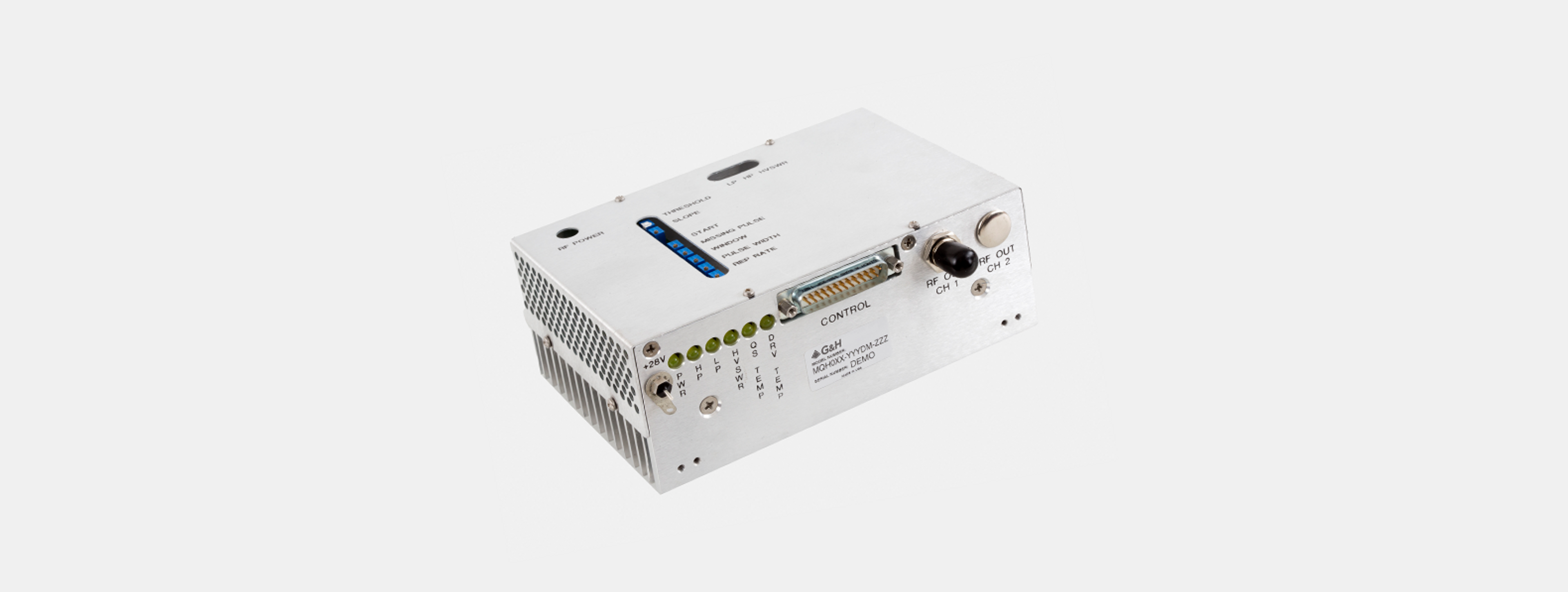
MQH0XX-YYDM-ZZZ
With an operating frequency of 24–110 MHz, a 100 W output into a 50-ohm load, and analog and digital modulation.
Full Product Description- Operating Frequency:
- 24 MHz, 27.12 MHz, 40.68 MHz, 68 MHz, 80 MHz
- RF frequency:
- 24.00, 27.12, 40.68, 68.00, 80.00 MHz ± 0.01%
- RF output power:
- Adjustable from 25 to 100 W, Nom: 50 W for 80 MHz units, Adjustable from 20 to 50 W.
Product description
This module is a high-power RF driver, designed to drive a Q-Switch.
The driver has two digital modulation inputs: fixed and variable. These controls allow the customer to issue a pulse command of fixed pulse width, the duration determined by the driver's pulse width control, settable by the customer, or issue a variable pulse command, the duration determined by the input signal’s pulse width.
The output power is controlled by the analog input, where the mode of operation is defined by ZZZ = A05 normal analog mode, or R05 analog switched to full RF mode or a triggered RF Ramp Down mode where ZZZ = FPS first pulse suppression mode or PPK pre-pulse kill mode. The choices of Frequency (XX), Output Power (YY), and Power Control (ZZZ) options are "Factory Set" when ordered.
This RF driver requires forced air cooling.
Key features
- 24, 27.12, 40.68, 68, 80, or 110 MHz RF frequency (XXX)
- 0.01% quartz stabilized
- Up to 100 W RF power output (YY)
- Analogue Modulation or Triggered RF Ramp Down Mode (ZZZ)
- Up to 100 kHz pulse rate
- Fault Protection on Low Power, High Power, and High VSWR
Specifications
| Name | Value |
|---|---|
| Operating Frequency | 24 MHz, 27.12 MHz, 40.68 MHz, 68 MHz, 80 MHz |
| RF frequency | 24.00, 27.12, 40.68, 68.00, 80.00 MHz ± 0.01% |
| Spurious levels | Max: -50 dBc |
| Harmonic distortion | Max: -30 dBc |
| Digital input | Fixed mod in: TTL Levels, Triggered on Rising Edge. Pulse Width Applied >50 ns., Variable mod in: TTL Levels, TTL High = RF off |
| Extinction ratio | Min: 35 dB |
| Rise/fall time | Max: 500 ns (10% to 90%), Max: 100 ns (90% to 10%) |
| Modulation repetition rates | 1 Hz to 100 kHz for fixed modulation, DC to 100 kHz for variable modulation |
| Fixed modulation output pulse width adjustment range | 1 to 14 µs, Customer Adjustable |
| FPS trigger / Analog input | Units configured with FPS, PPK: TTL levels, Triggered on TTL rising edge. Units configured with A05, R05: 0 to 5 V analog. |
| RF output power | Adjustable from 25 to 100 W, Nom: 50 W for 80 MHz units, Adjustable from 20 to 50 W. |
| Output impedance | Nom: 50 Ω |
| Shutter output | 0.3 sec delay. Opens on fault. Capable of sinking max: 1 A at 28 V. |
| Supply voltage | +28 VDC ± 1% |
| Supply current | 6.5 A for 50 W units, 9.0 A for 100 W units |
| Operating temperature | +10°C to +55°C |
| Air flow through heat sink | > 36 CFM (> 17 litres / second) @ 25°C |
| Available pulse control options | ZZZ | Mode |
|---|---|---|
| Pulse control mode is "Factory set when ordered": | FPS | First pulse suppression |
| PPK | Pre pulse kill | |
| A05 | Analog control | |
| R05 | RF switched to analog control | |
| ___ | Digital modulation only |
| Maximum ratings | |
|---|---|
| Supply voltage | Max: 30 V DC |
| Power output | No DC feedback allowed |
| Storage temperature: | -20°C to +85°C |
| Connectors and mechanical | ||
|---|---|---|
| RF output connector | BNC Female | |
| Power supply connections | Vcc | Solder Post |
| Return | Ground Lug |
25pin D-Sub connector pinout
Located on front panel.
| Pin assignment | |||||
|---|---|---|---|---|---|
| Pin 1 | +5V | +5V output for external fault indicators, 75 mA available. | Pin 12 | MOD IN ANALOG | Controls the output power level in A05 and R05 models |
| Pin 2-3 | NC | No connection. | Pin 13 | FAULT RESET | Pulse LOW to reset the driver from a fault condition. This line should not be held LOW or it will defeat some of the fault conditions. |
| Pin 4 | THERM RTN | Ground – to be used as a return for THERM. | Pin 14 | FPS TRG | Triggers a suppression pulse on a RISING edge. |
| Pin 5 | NC | No connection. | Pin 15 | MOD IN FIXED | Turns the driver off for the duration set by the pulse width control. |
| Pin 6 | THERM | Thermostat connection – driver enters a fault condition unless this is Shorted to ground. | Pin 16 | MOD IN VARIABLE | Turns the driver off while this input is HIGH. |
| Pin 7 | DRV TEMP | Normally HIGH, goes LOW when the driver is in an overheat fault. | Pin17 | SYNC OUT | Outputs a signal synchronized to the modulation output. |
| Pin 8 | QS TEMP | Normally HIGH, goes LOW when no short present on THERM. | Pin 18-19 | NC | No connection |
| Pin 9 | HVSWR | High VSWR fault, normally HIGH, goes LOW during fault. | Pin 20 | SHUTTER | 0.3 sec delay. Opens on fault. Capable of sinking 1 amps at 28 volts maximum. |
| Pin 10 | LP | Low RF Power indicator, normally HIGH, goes LOW while driver output is below the Low RF Power threshold. | Pin 21-24 | NC | No connection. |
| Pin 11 | HP | High RF Power fault, normally HIGH, goes LOW during fault. | Pin 25 | GND | Ground |
| Indicators | Located on front panel |
|---|---|
| Power | Power Indicator – The module has 28 V applied on the DC connector. |
| Low Power | Faults after 0.3 second, power below LP Set Point. Resets on power adjusted above Set Point. |
| High Power | Faults when power above HP Set Point. Reset required after removing fault. |
| High VSWR | Faults when reflected power above VSWR Set Point. Reset required after removing fault. |
| QS Temp | Faults on open Thermostat. Resets on closed Thermostat. (Q-Switch below set temperature) |
| DRV Temp Driver | The internal temperature of the module has reached 60C. The driver will remain in this fault condition until it cools down. |
| Adjustments | Located inside unit through holes in module top cover |
|---|---|
| RF Power Level Adjustment | Adjusts the output RF Power. |
| LP Set Point | Adjusts the minimum power threshold. If the module’s output goes Below this set value, the low power warning light will turn on, but the driver will continue to output power. This is a warning, not a true fault condition. |
| HP Set Point | Adjusts the maximum power threshold for the module. If the output rises above this threshold, the module will cease output until it is reset. |
| VSWR Set Point | Adjusts the module’s tolerance for a mismatched load connected to RF Out. If a mismatch is detected, the driver will cease outputting power until reset. |
| Pulse Width | Adjusts the length of time the driver outputs no RF energy after receiving a trigger. 1s to 14s. |
The following adjustment is not used on units configured with FPS or PPK:
| Threshold | Sets the point below which the analog voltage is ignored and the system output is shut off. |
The following adjustments are not used on units configured with Analog Input (A05, R05):
| FPS Start | Adjusts the initial power level of the first pulse. |
| FPS Slope | Adjusts how quickly the RF pulses return to their normal level after the FPS has been triggered. 20 µs to 300 µs. |
| FPS Window | Adjusts the duration of the suppression pulse cycle. 20 µs to 300 µs. |
Order code
Output frequency is "Factory Set When Ordered"
XX = 24, 27, 41, 68, or 80.
YY = 50 or 100 W nominal for 24, 27, 41, and 68 MHz units.
ZZZ = Mode (see table)