A35XXX-S-1/50-P4K7U
With an operating frequency of 40–300 MHz, a 5 W output into a 50-ohm load, and analog and digital modulation, with a rise time as low as 4 ns.
Full Product Description- RF output power:
- Max: > 5 W (+37 dBm) (adjustable), Adjustment range: < 0.1 W … > 5 W *
- RF output frequency:
- 40 … <80 MHz, 80 … <140 MHz, 140 … <200 MHz, 200 … 350 MHz ***
Product description
Additionally to the analog modulation voltage a digital modulation control signal can switch on and off the RF power. Both the analog and digital modulation are characterized by extraordinary on/off ratios of at least 65dB.
The driver can be operated with modulation frequencies (analog and digital) up to 25% of the carrier frequency and 50 MHz maximum.
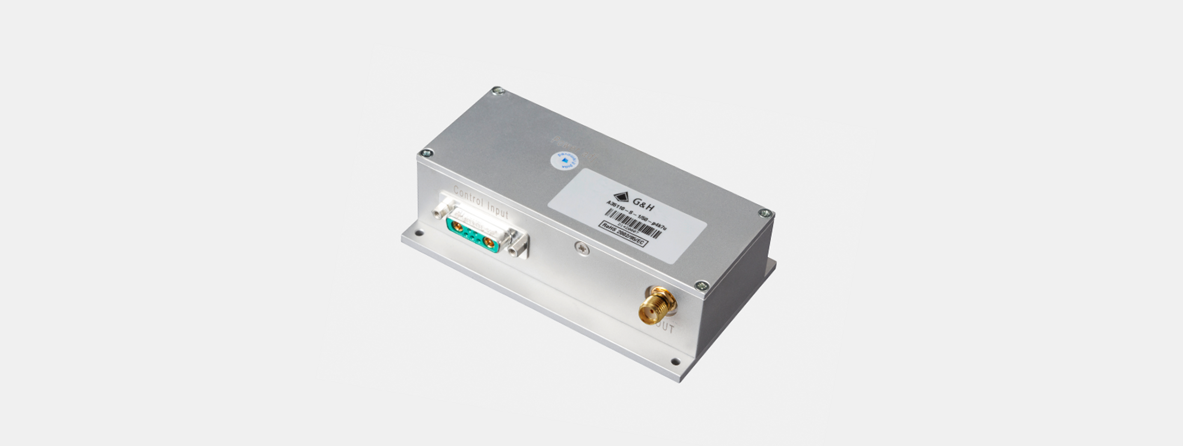
Optimum EMC shielding and mechanical protection are achieved by an aluminum casing. The base plate serves for mounting as well as for heat dissipation.
Key features
- Constant output power design
- Models with a modulation frequency up to 50 MHz available
- Conductive cooling through base plate
- Compact casing, fully shielded (EMC)
Specifications
| Name | Value |
|---|---|
| RF output power | Max: > 5 W (+37 dBm) (adjustable), Adjustment range: < 0.1 W … > 5 W * |
| Supply voltage | +24 VDC |
| Supply current | Typ: 1.5 A @ 5 W RF output power |
| Output impedance | Nom: 50 Ω |
| Frequency accuracy | < ±25 ppm |
| Harmonics distortion | < -26 dBc * |
| Analogue modulation impedance | 50 Ω ** |
| Analogue modulation voltage range | 0 … +1 V @ 50 Ω ** |
| Analogue modulation RF ON / OFF ratio | > 65 dB ** |
| Digital modulation impedance | 4.7 kΩ (pull-up) ** |
| Digital modulation level | High = ≥ 3V … 5V (= RF on) **, Low = 0 … < 2V (= RF off) ** |
| Digital modulation RF ON / OFF ratio | > 100 dB ** |
| RF output frequency | 40 … <80 MHz, 80 … <140 MHz, 140 … <200 MHz, 200 … 350 MHz *** |
| Cooling | Conduction. The base plate must be attached to a suitable heat sink capable of dissipating 36 Watt. |
| Dimensions | Casing: 120 x 50 x 36 mm ****, Mounting flat: 120 x 70 mm |
| Weight | 360 grams |
| Warm-up time | 10 minutes for optimum stability |
| Base plate temperature | +10° C … +60° C. For optimum output power stability, constant base plate temperature should be provided. |
| Storage temperature | -20° C … +70° C, non condensing |
| Supply voltage | Absolute max: +26 VDC |
| Analogue modulation voltage range | Absolute max: -0.5 V … +1.1 V @ 0 … +1 V |
| Digital modulation level | Absolute max: -0.5 V … +5.5 V |
| Operating temperature | Absolute max: +65°C base plate temperature |
| Analogue modulation | ||||
|---|---|---|---|---|
| RF rise time / fall time | < 25 ns | < 15 ns | < 10 ns | < 8 ns |
| (P RF: 10 … 90%) * |
| Digital modulation | ||||
|---|---|---|---|---|
| RF rise time / fall time | < 25 ns | < 15 ns | < 10 ns | < 8 ns |
| (P RF: 10 … 90%) * |
* into 50 Ω load
** other configurations on request
*** standard frequencies: 40, 80, 110, 150, 200 MHz
**** length x width x height
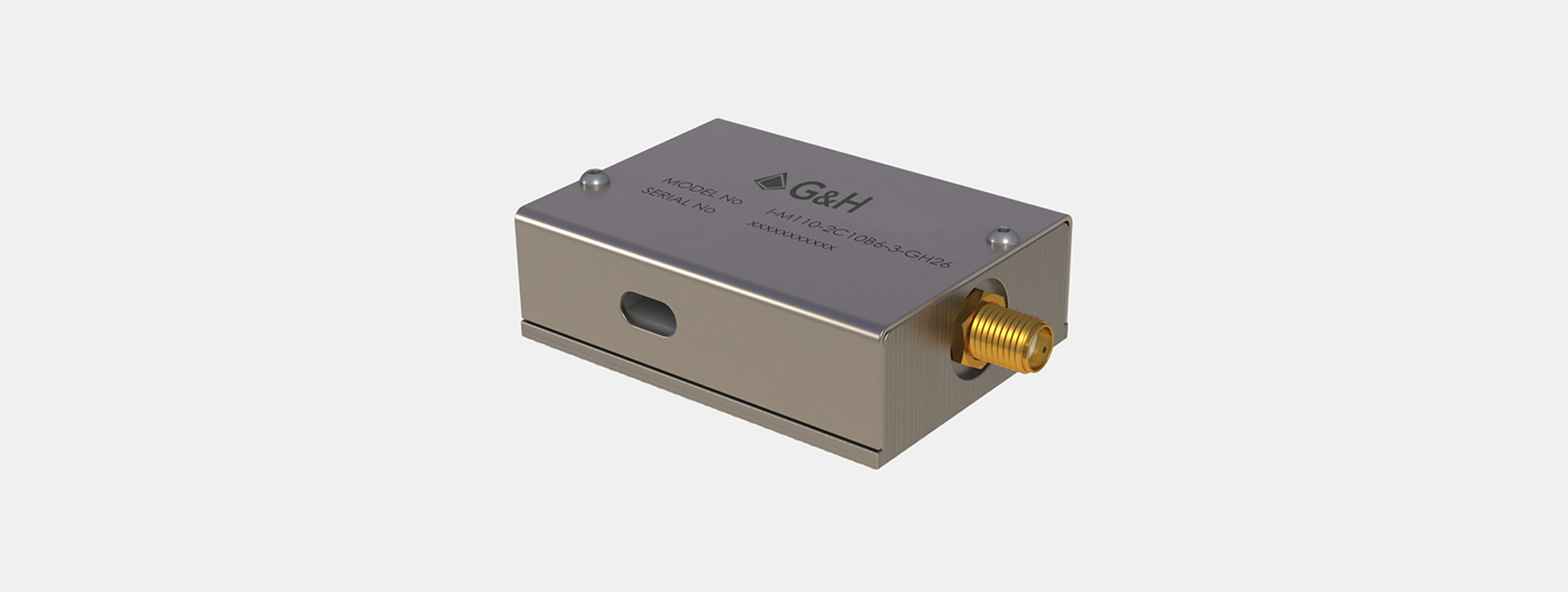
Connectors
| RF output connector | SMA female |
|---|---|
| Control input connector | D-Sub 7W2 |
| Pins 1 and 2, inside linked | GND (case) |
| Pins 3 and 5, inside linked | +V s (24 VDC) |
| Pin 4 | not connected |
| Pin A1 (coaxial) | Analogue modulation |
| Pin A2 (coaxial) | Digital modulation |
Quality Standards
| EU 2002/95/EC (RoHS) | compliant |
|---|---|
| EMC standards | VDE 0871-B |
| FCC Rules Part 15-B | |
| Thermal test | 2h @ 70°C passive |
| Burn-in test | 30 minutes @ maximum RF power output |