
High Reliability Fused Coupler 980nm Band
For combining and monitoring signals at the wavelengths of 960, 980 or, 1060 nm in harsh environments such as undersea and space, where the costs of component replacement are prohibitive, for wavelengths
Full Product Description- Operating wavelength:
- 960 nm: 955 – 965 nm, 980 nm: 975 – 985 nm, 1060 nm: 1055 – 1065 nm
- Optical power handling:
- 4 W
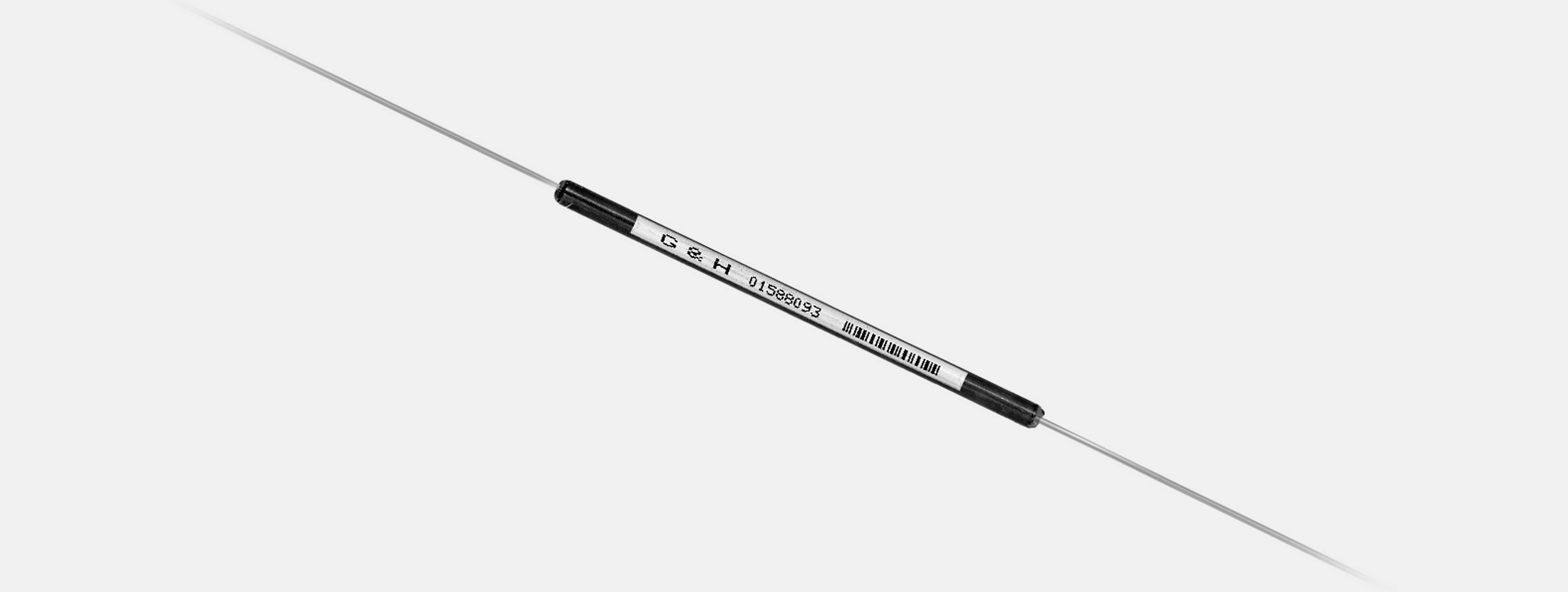
Product description
Using our proven fused biconical taper process, our HI REL capability is built upon the foundation of the long-established manufacturing history of very reliable terrestrial components.
The ultra-low loss of our fused fiber components helps to promote low noise and improved system margin in undersea transmission systems.
Full facilities are available to perform customer-specific HI REL qualification programs, which can consist of accelerated aging and Weibull analysis. Our design standard is 0.1 FITs, meaning failure-free operation for one billion field hours.
Manufacturing is carried out on specially-developed workstations, and advanced fiber management, in-process screening, and customer-specific validation tests are implemented, to further enhance component reliability. Components are supplied in regular or custom housings, depending upon the installation environment.
Key features
- High Power Handling
- Low loss
- Design standard 0.1 FITs (failure in one billion field hours)
Specifications
| Name | Value |
|---|---|
| Operating wavelength | 960 nm: 955 – 965 nm, 980 nm: 975 – 985 nm, 1060 nm: 1055 – 1065 nm |
| Return loss/directivity | 55 dB ¹ |
| Pigtail tensile load | 5 N ² |
| Optical power handling | 4 W |
| Environmental qualification | Component design to 0.1FIT Failures in 10⁹ hours |
¹ Return loss is the ratio of power launched to power reflected for port P1. Directivity for the 2x2 component is the ratio of power launched to P1 to the power reflected to P4. Guaranteed by design.
² Stripped fiber proof tested on rig to confirm strength.
Optical specifications
| Coupling Ratio | Example ⁴ | 5% | 10% | 50% | |
|---|---|---|---|---|---|
| Grade | H | H | H | ||
| Signal Path | Insertion Loss ¹ ² | Min | 2.5 | ||
| Max | 0.50 | 0.75 | 3.6 | ||
| TDL ³ | Max | 0.08 | 0.08 | 0.10 | |
| Tap Path | Insertion Loss ¹ ² | Min | 11.0 | 8.5 | 2.5 |
| Max | 15.2 | 11.8 | 3.6 | ||
| TDL ³ | Max | 0.15 | 0.13 | 0.10 |
¹ Insertion loss over operating wavelength range and component life - not including PDL, TDL (25 years, typical service/storage conditions 40° C / 60% RH).
² In 2x2 couplers insertion loss is not specified for launch through second input port P4 (colored blue).
³ Change in insertion loss from -5 – +75ºC. Guaranteed by design.
⁴ Any coupling ratio available – contact G&H for specification of coupling ratios not listed.
Order code
Guidance on how to create an order code is available in Downloads below.